01 / Short answer
Use two measurements, then confirm the standard.
Measure the external thread's major diameter with a suitable caliper, then match the thread spacing with the correct pitch-gauge leaf. Metric machine threads use pitch in millimeters; common US Unified threads use threads per inch (TPI).
Coating, damage, dirt, worn crests, access, and measuring pressure can distort the reading. Compare the result with a trusted table or the equipment documentation.
02 / Major diameter
Measure across the outside thread crests.
For a normal external machine thread, the nominal diameter is based on the major diameter across the thread crests. Clean loose debris without removing material, measure at several intact locations, and record the readings with their units. Keep nearby metric and inch sizes as candidates until the spacing is checked. A nominal diameter is a reference size, not a promise that every actual crest will measure exactly that value.
This outside-crest check applies to an accessible external thread. Caliper jaws inside a threaded hole do not give the same major-diameter measurement. If you cannot reach intact threads, use the equipment drawing or ask for qualified identification instead of adapting this check by guesswork.
- Do not identify the thread from the hex-head wrench size.
- Do not measure only one flattened or visibly damaged crest.
- Do not assume an inch-looking diameter rules out a nearby metric size.
03 / Pitch or TPI
Metric and inch systems describe spacing differently.
| System | Spacing value | Example notation | Meaning |
|---|---|---|---|
| Metric | Pitch in millimeters | M8 × 1.25 | 8 mm nominal diameter, 1.25 mm from one thread to the next. |
| US Unified / inch | Threads per inch | 1/4-20 | 1/4-inch nominal diameter, 20 threads in one inch. |
People often say “SAE” when they mean an inch-series fastener. The complete identification still needs the actual diameter, TPI, series/form, and fit.
04 / Worked reference example
Near 8 mm does not settle M8 vs 5/16 inch.
Bolt Depot's supplier reference tables list the following nominal sizes and spacing values. They are useful comparison candidates for a common machine thread, not measurements of your part or a complete list of nearby thread forms.
| Designation | Nominal diameter, as listed | Spacing, as listed | Editorial conversion to millimeters |
|---|---|---|---|
| M8 × 1.25 | 8 mm | 1.25 mm pitch | Diameter: 8 mm; pitch: 1.25 mm |
| 5/16-18 UNC | 5/16 inch | 18 TPI, Unified coarse | Diameter: 7.9375 mm; pitch: approximately 1.4111 mm |
| 5/16-24 UNF | 5/16 inch | 24 TPI, Unified fine | Diameter: 7.9375 mm; pitch: approximately 1.0583 mm |
Table references: Bolt Depot's metric pitch table and US TPI table. These are supplier reference charts, not a standards document or manufacturer approval for your component.
Using NIST's exact 25.4 mm per inch definition, the diameter conversion is (5 ÷ 16) × 25.4 = 7.9375 mm. For inch threads, pitch in millimeters = 25.4 ÷ TPI. These are calculations from the table, not readings from a tool.
8 − 7.9375 = 0.0625 mm. That arithmetic does not account for thread tolerances, coating, wear, damage, tool accuracy, or access. Do not round a reading to 8 mm and call it M8. The listed spacings differ; check the actual pitch or TPI marking and the equipment specification.
This example does not exclude M8 × 1.0 or other metric pitches, numbered inch screws, British thread forms, or pipe threads. “SAE” is everyday shorthand here for common US Unified inch machine threads, not a label for every inch thread.
05 / Read the spacing
Five consecutive crest positions make four intervals.
Pitch is the distance along the screw axis between corresponding points on adjacent threads. The original schematic below uses dots for consecutive crest reference positions; it does not draw a thread profile or a physical part.
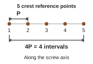
For the listed M8 × 1.25 reference, four intervals would span 4 × 1.25 = 5.00 mm by arithmetic. Count the spaces between matching positions, not the number of visible crests. A rough ruler comparison can suggest a candidate; it does not certify the pitch or establish a tolerance.
Record the marking on a suitable pitch-gauge leaf in its original units. A leaf marked 1.25 refers to millimeter pitch when the tool identifies it as metric; an inch leaf marked 18 refers to 18 TPI. Converting the units does not make those two spacings interchangeable.
06 / Read the notation
Do not drop the spacing value.
“M8” alone does not distinguish M8 × 1.25 from an M8 fine pitch such as M8 × 1.0. Likewise, “1/4 inch” does not distinguish 1/4-20 from 1/4-28. A repair kit, nut, insert, or tap must match the full thread designation—not just the diameter.
07 / Using a pitch gauge
Compare several intact threads and keep the leaf marking.
- 1
Clean and inspect
Remove loose debris and stop if the crests are torn, stretched, or crossed.
- 2
Try the likely system
Use metric leaves for millimeter pitch and inch leaves marked in TPI.
- 3
Look across several threads
The leaf profile should seat repeatedly without a growing mismatch.
- 4
Confirm against a table or known part
Compare both observations with a documented designation. A familiar nut or bolt with an unknown specification is not a reliable reference.
A pitch match is an identification clue, not a check of pitch diameter, tolerance class, thread damage, or load capacity. If you are choosing a tool, the pitch gauge vs thread checker guide explains what each type can establish and what needs separate inspection.
08 / Stop conditions
Never use force as an identification method.
- Stop if a nut or bolt starts tightly after only partial engagement.
- Stop if the pitch-gauge fit is ambiguous because the thread is damaged.
- Stop if readings disagree, too few intact threads are visible, or the gauge cannot seat because access is blocked.
- Stop if the observations cannot distinguish nearby candidates; do not invent a rounding rule or an acceptable error.
- Stop if the form, taper, handedness, or equipment specification is uncertain.
- Stop before cutting when the parent material, thread form, or approved repair is unknown.
- Escalate safety-critical or load-bearing joints to the current service procedure or a qualified professional.
Identifying a thread does not tell you whether it needs an insert. If you are still assessing the damage, follow the chase, tap, insert, or stop decision guide before choosing a kit.
09 / Keep an identification record
Record what you observed before choosing a replacement.
Keep observations separate from reference values. This blank record does not turn an uncertain reading into a confirmed specification.
| Field | What to record |
|---|---|
| Part and access | Equipment and part reference; external or internal thread; loose or installed; visible obstruction. |
| Condition | Dirt, coating, wear, damaged crests, and which intact locations you can reach. |
| Diameter observations | Each accessible external-crest reading, units, tool model, and measuring locations. Leave unknown values unknown. |
| Spacing observations | Metric pitch or inch TPI exactly as marked on the leaf; fit across several intact threads; any ambiguity. |
| Reference and candidate | Equipment drawing or supplier chart, complete designation, and other candidates you have not excluded. |
| Unresolved requirements | Form, taper, handedness, tolerance class, part specification, and any required calibrated inspection or service approval. |
| Decision | Identification supported by documentation, or unresolved—stop and request qualified identification. Record the date and supporting photos if available. |
For a safety-critical joint, use the manufacturer's current service procedure or a qualified professional. Even a confirmed nominal designation does not establish the required grade, material, coating, length, torque, or repair approval.
10 / Sources and scope
A field workflow, not dimensional inspection certification.
This guide helps narrow common machine threads. It does not replace calibrated thread metrology, plug/ring gauges, engineering drawings, or manufacturer service information when acceptance limits matter.
The worked comparison was checked October 7, 2026. We have not measured parts or tested tools for this guide. Listed sizes come from the linked supplier tables; conversions and the spacing schematic are editorial calculations. The workflow and stop conditions are conservative editorial guidance, not a manufacturer procedure or a dimensional acceptance standard.
- Bolt Depot — metric thread pitch table8 mm row: standard 1.25 mm pitch and fine 1 mm pitch; nominal reference values.
- Bolt Depot — US threads per inch table5/16-inch row: 18 TPI in the UNC column and 24 TPI in the UNF column.
- NIST — SI units of lengthExact 25.4 mm per international inch conversion, used for the editorial arithmetic.
- Fastenal — metric system and specificationsMetric M notation, millimeter pitch, and inch threads-per-inch explanation.
- Portland Bolt — inch thread pitch chartAdditional common Unified-series reference; not the source for the 5/16-inch rows above.
- Bossard — metric thread profile calculatorStandards-based metric major, pitch, and minor diameter terminology.