Research / editorial guide. Documentation checked October 20, 2026; no wrench or attachment was purchased, measured, or tested for this guide. As an Amazon Associate I earn from qualifying purchases. This guide has no Amazon product links. See our affiliate disclosure.
Start with the wrench and its manual
Read the model marking before copying a dimension from a listing. Save the instructions that apply to that exact model, including any revision shown in the document. A manual for another wrench that looks similar is not a substitute.
The TRQ61122 manufacturer page linked to the split-beam manual checked for this guide. Its model table lists both examples below. The filename contains 091626; we have not established a printed revision date from that filename.
| Model in this manual | Effective length, L | Overall length |
|---|---|---|
| TRQ61122 | 15.6 in. | 18.8 in. |
| TRQ62122 | 19.2 in. | 22.8 in. |
These are manufacturer-listed dimensions, not our measurements. The manual's printed page 1 supplies the table; pages 5–6 explain the correction. Overall length is a different dimension and should not be entered as L. Both listed models measure clockwise only, according to printed page 4. Do not infer measuring direction from whether an attachment can physically turn a fastener.
For another model or brand, start a fresh record using its own instructions. Do not carry either example's length into that record.
Locate the centers, then give C a sign
In the source manual, L runs from the square-drive center to the handle center. TEKTON's crowfoot explanation describes the handle reference and measuring procedure. Follow the instructions for your wrench, especially if its handle position changes with the setting.
C is the attachment's change along a line parallel to the wrench body. It is positive when the fastener center extends farther away from the handle than the drive center, negative when it moves toward the handle, and zero when those centers have the same position along that direction. An angled center-to-center distance is not that parallel change.
The following original diagrams show only reference centers in a flat view. H means handle center, D means square-drive center, and F means fastener center. The line connecting D and F indicates their relationship, not an attachment's physical outline. The diagrams are not to scale and are not product photographs or test evidence. Their definitions follow the manual's printed pages 5–6.
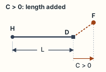
Positive C: the fastener's projected position lies beyond the square drive. The effective distance is increased.
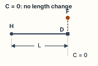
Zero C: the fastener and drive centers align across the wrench axis. There is no parallel length change in this geometry.
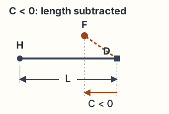
Negative C: the projected fastener center moves toward the handle. Keep the minus sign with the value.
Read the formula as an input check
For the configuration covered by the source instructions:
T2 = T1 × L / (L + C)
T1 is the equipment's required fastener torque; T2 is the corrected wrench setting. L and C must use the same length unit. T1 and T2 retain the same torque unit. The source formula assumes a straight head and handle, with a flex head not engaged.
The following checks are algebraic consequences of that formula, not measured tool performance:
| Input relationship | Expected calculation trend | Error to investigate |
|---|---|---|
| C is positive | T2 is less than T1 | A result above T1 suggests a sign, input, or formula error |
| C is zero | T2 equals T1 | A changed answer suggests the wrong C was entered |
| C is negative and L + C remains positive | T2 is greater than T1 | A lower result suggests the negative sign was lost |
Stop if L is not positive, L + C is not positive, a required reference point is uncertain, or the setup falls outside the instructions. A numerical answer cannot resolve an unknown geometry.
There is no equipment torque example here. Obtain T1 from the equipment manufacturer's applicable procedure, including its fastener and assembly conditions. For safety-critical work, use that procedure and qualified help.
Keep a worksheet with the setup
Use this editorial checklist before calculating. A missing entry is a question to resolve with the applicable manufacturer, not a number to guess.
| Field | What to record | Stop and resolve if… |
|---|---|---|
| Wrench identity | Manufacturer, full model, and matching manual | The available instructions name a different model |
| Required torque, T1 | Equipment procedure, torque unit, and specified conditions | The torque or procedure is unknown |
| Effective length, L | The manual's value or prescribed measurement, reference points, and length unit | Only overall length is available |
| Attachment change, C | Actual orientation, parallel change, sign, and the same length unit as L | Only an angled distance or outside dimension is known |
| Permitted configuration | Attachment suitability, measuring direction, and head position | Compatibility or the formula's applicability is unresolved |
| Calculated setting, T2 | Formula, inputs, result, and torque unit | The answer contradicts the sign check or uses mixed units |
| Usable setting | Model's permitted range and ability to set the required result | The corrected value is outside the range or cannot be set as required |
Keep the worksheet with a sketch or photograph of your actual orientation. If the attachment rotates to a different position, revisit C; do not reuse an answer merely because the same two tools are attached.
Check the corrected setting against the wrench's instructions before proceeding. Do not silently round a result to a convenient mark and call that an approved setting. If the required setting cannot be selected, resolve the method with the applicable manufacturer or use an approved alternative setup.
For unit changes, our torque converter can help with arithmetic. It does not determine T1 or approve a crowfoot configuration. Our torque range checker also cannot establish that an attachment method is valid.
Where the shortcut stops
“Put it at 90 degrees” is useful only when the actual centers give C = 0 and the manufacturer's other conditions are satisfied. Check the centers and instructions rather than relying on the outside edges of the tools.
This worksheet covers the drive-end attachment question. It does not cover a pipe or extension added to the handle; the cited manual prohibits handle extensions. Nor does it extend the flat-geometry formula to an engaged flex head or an arbitrary stack of adapters.
The calculation is separate from the condition and calibration of your wrench. A matching number does not prove accuracy, attachment strength, or suitability for a particular fastener. Use our calibration-certificate reading guide for the separate paperwork question. If you are choosing the basic type of torque tool, start with torque screwdriver versus torque wrench.
Sources and limits
- TEKTON Split Beam Torque Wrenches product manual: printed page 1 for model dimensions; pages 2–4 for handle reference, use restrictions, and direction; pages 5–6 for the correction and signed length change.
- TRQ61122 manufacturer page: exact model and the manual link checked October 20, 2026. This is a documentation example, not a stock or buying recommendation.
- TEKTON: How to Use a Torque Wrench with a Crowfoot Wrench: input definitions and the straight-head condition.
The worksheet, sign checks, and abstract center diagrams are our editorial explanation of these sources. They do not establish cross-brand compatibility, an equipment torque specification, calibration results, or a safe application. The manufacturer artwork is not reproduced here.